Chemical Engineering Drawing at Explore collection of Chemical Engineering
On the Data tab, click Shape Data Window. On the drawing page, select the shape to which you would like to add data. Click in each shape data field, and type or select a value. Create and apply property sets. Do one of the following: To add the property set to shapes on a drawing, select the shapes.
Chemical and Process Engineering Solution
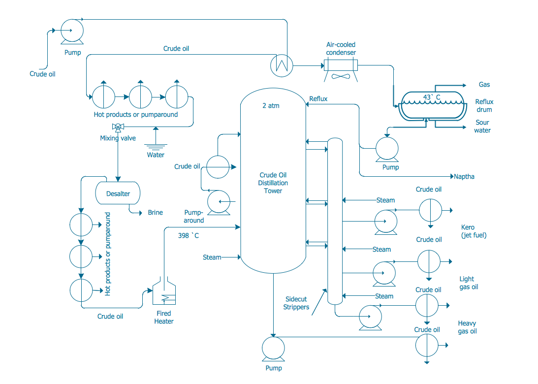
Generally, a Process Flow Diagram shows only the major equipment and doesn't show details. PFDs are used for visitor information and new employee training. A Process and Instrument Drawing (P&ID) includes more details than a PFD. It includes major and minor flows, control loops and instrumentation. P&ID is sometimes referred to as a Piping and.
ConceptDraw Samples Engineering — Chemical and process
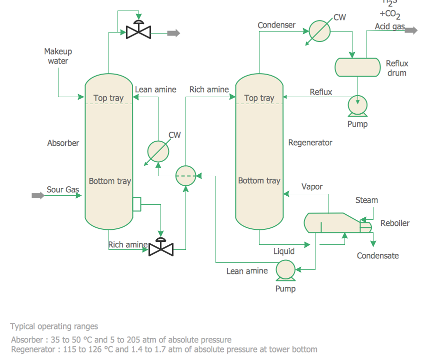
This chemical engineering solution extends ConceptDraw DIAGRAM.9.5 (or later) with process flow diagram symbols, samples, process diagrams templates and libraries of design elements for creating process and instrumentation diagrams, block flow diagrams (BFD Chemistry Diagrams

Creating a Create a Chemical Process Flow Diagram ConceptDraw HelpDesk
Extending the ConceptDraw DIAGRAM diagramming and drawing software with process flow diagram symbols, samples, process diagrams templates and libraries of de.

The Chemical Process Industry for Dummies ) on Behance
Process Flow Diagram widely used in modeling of processes in the chemical industry. A Chemical Process Flow diagram (PFD) is a specialized type of flowchart. With the help of Chemical Process Flow Diagram, engineers can easily specify the general scheme of the processes and chemical plant equipment. Chemical Process Flow Diagram displays the real scheme of the chemical process, the.
Chemical and Process Engineering Solution
Diagram Name. RESUME SESSION IMPORT Excel .csv. END SESSION. GENERATE Table. EXPORT Table as Excel .csv. Process Flow Diagram Tool for MUChemical Engineering.
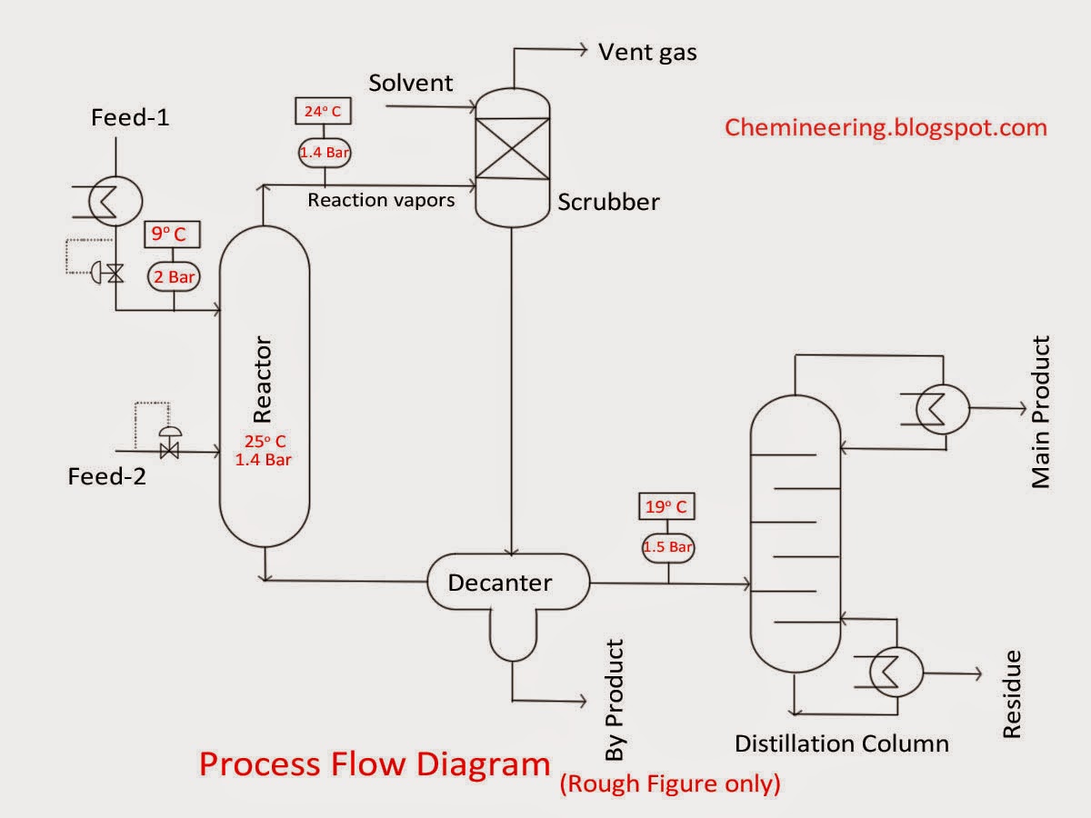
Chemineering Types of Chemical engineering drawings BFD, PFD, P&ID
Open API The SmartDraw API allows you to skip the drawing process and generate diagrams from data automatically. Shape Data Add data to shapes, import data, export manifests, and create data rules to change dashboards that update. Explore SmartDraw Check out useful features that will make your life easier.
.jpg)
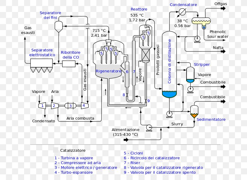
Chemical reactors
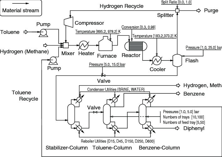
Introduction. The process flow diagram (PFD) is a critical component of process design. It is absolutely necessary that chemical engineers know how to read process flow diagrams because it is the primary method of detailing the process and design information. Additionally, the most effective way of relaying information about a process design is.
How to Draw a Chemical Process Flow Diagram Process Flow Diagram Symbols How to Draw
Process Flow Diagram widely used in modeling of processes in the chemical industry. A Chemical Process Flow diagram (PFD) is a specialized type of flowchart. With the help of Chemical Process Flow Diagram, engineers can easily specify the general scheme of the processes and chemical plant equipment. Chemical Process Flow Diagram displays the real scheme of the chemical process, the.
Chemical Plant Process Flow Diagram Haber Process Chemical Industry, PNG, 706x599px, Chemical
The latest update of Visual Paradigm Online offers effective diagramming solutions that support the need of chemical and process engineering. Two new diagram types are now available: Process Flow Diagram tool and P & ID tool . Visual Paradigm Online supports a rich set of high-quality Process Flow Diagram (PFD) and Piping and Instrumentation.

176 questions with answers in CHEMICAL STRUCTURE Science topic
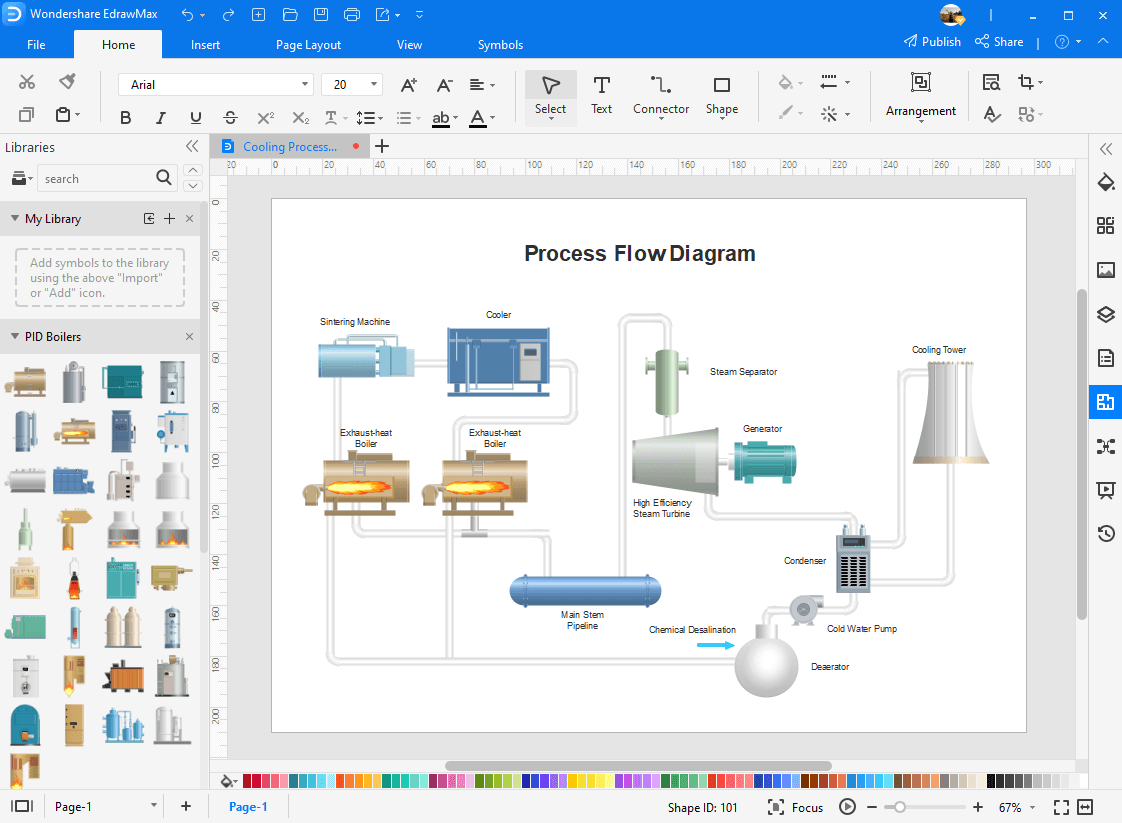
That said, listed below are the five best process flow diagram software that can help you create perplexing PFDs within a couple of minutes with ease: 1. EdrawMax. The first process flow diagram software on the list that is both low in price and easy to work with is EdrawMax. This tool is available for almost all major platforms, along with a.

Creating a Create a Chemical Process Flow Diagram ConceptDraw HelpDesk
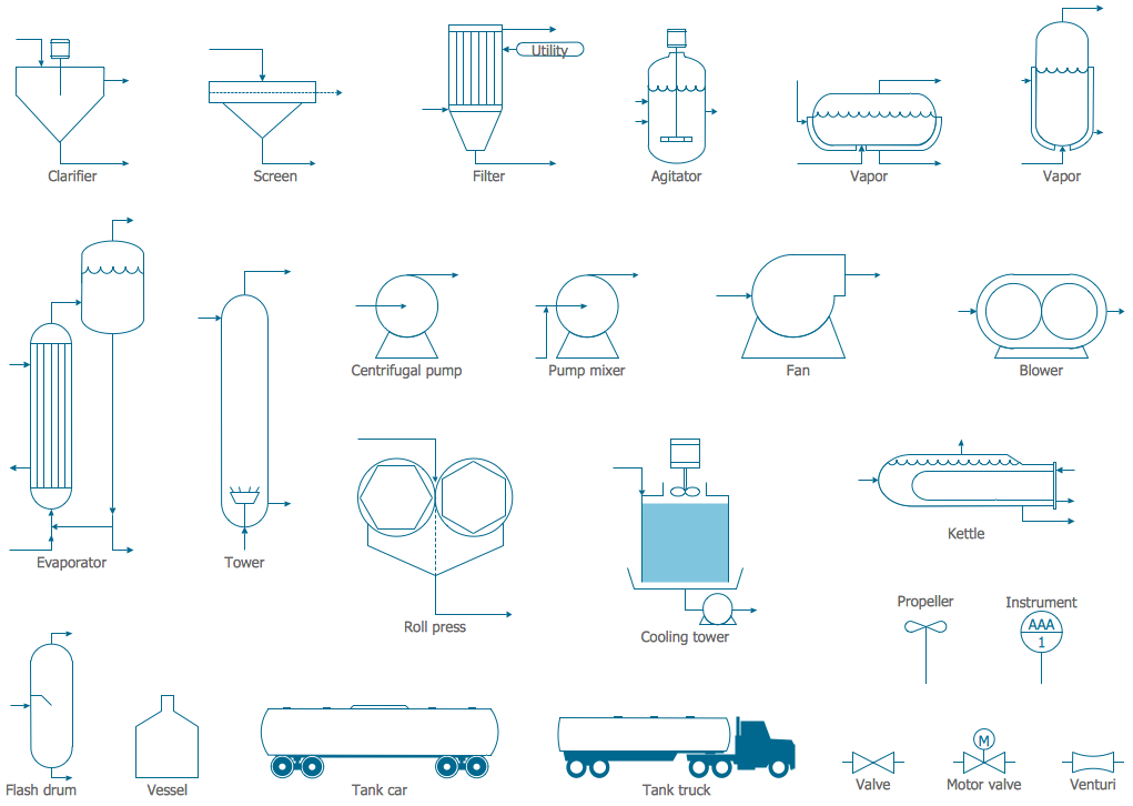
Select libraries from the Chemical Process Engineering libraries on the Solutions panel. Add objects to the drawing by dragging them from the libraries panel to the document page. Use a diverse set of connectors to connect the diagram elements. Select a proper connector from the diverse set of connectors on the drawing tools panel.
Chemical and Process Engineering Solution
A block flow diagram (BFD) is a drawing of chemical processes used to simplify and understand the basic structure of a system suggested by Peters & Timmerhaus, in 2003. A BFD is the simplest form of the flow diagrams used in the industry. Blocks in a BFD can represent anything from a single piece of equipment to an entire plant.
Chemical Process Drawing Software QuyaSoft
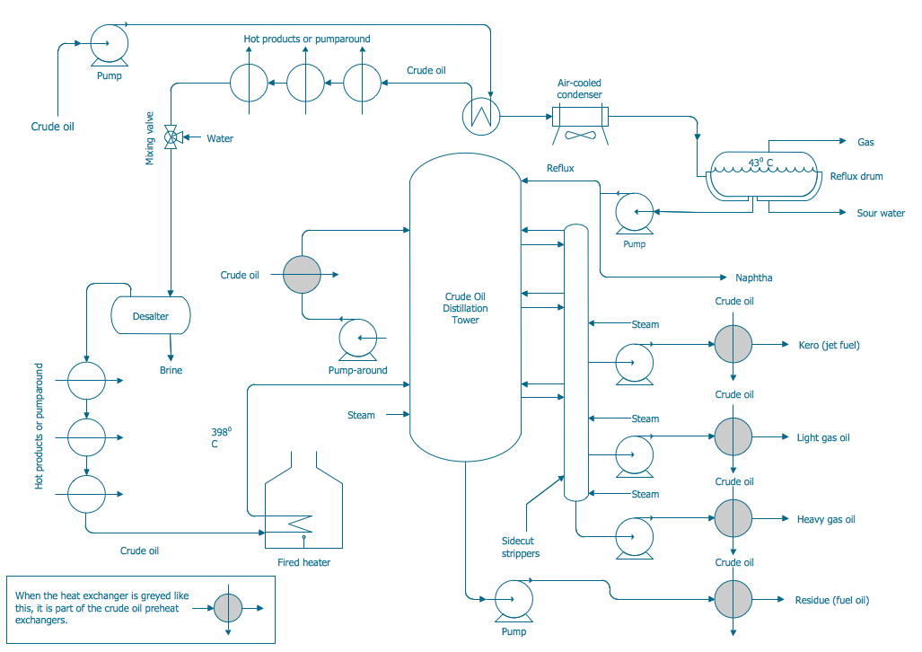
A process flow diagram is a graphical tool most commonly used by business process management professionals (BPM) and chemical engineers. PFD helps to understand the process, provide quality control, and increase efficiency. It is used to get a top-down understanding of how different types of equipment and chemicals work in the industrial plant.

Chemical process Royalty Free Vector Image VectorStock
A Process Flow Diagram (PFD) is a type of flowchart that illustrates the relationships between major components at an industrial plant. It's most often used in chemical engineering and process engineering, though its concepts are sometimes applied to other processes as well. It's used to document a process, improve a process or model a new one.
Chemical Process Diagram (Lec04) YouTube
Chemical/Process Engineering Drawings are the drawings that can show terminals, platforms or plants in small sizes. Within these drawings, some standardized symbols can be used to interpret and understand the plant data easier .